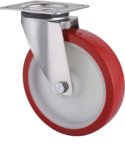
Trolley Castor Layouts: Swivel, Fixed and Braked Castors
Compare trolley castor layouts for straight routes, tight turns and sideways positioning. Understand central-wheel designs, brake functions and the checks needed before specifying an OEM trolley.
Key takeaways
- Start by comparing two swivel plus two fixed castors with four swivel castors; choose according to the route and positioning task.
- Three-point, central-wheel and six-wheel layouts require their own contact and load assessment.
- Swivel and fixed describe steering construction; brakes and locks add functions. Specify the required rolling and steering state.
- Validate the assembled trolley under representative loads before freezing its castor specification.
Define the route before choosing the layout
A platform trolley travelling between stores and an assembly line has a different steering task from a roll cage that must move sideways into a loading position. Sketch the complete journey: straight sections, aisle widths, doorways, turns, docking points and parking areas. Mark where an operator can stand and apply force without stepping into an obstruction.
Record trolley mass, maximum payload and where that payload can sit, including partial unloading. A tall load or an item placed near an edge can change handling even when total mass is unchanged. Specify manual movement separately from towing: a layout sketch does not establish permissible towing speed, train behaviour or coupling loads.
The HSE pushing and pulling guidance identifies route clearance, load stability, floor condition and effective brakes as assessment factors. Use these to define the trial conditions, alongside wheel material and bearing selection in the wider castor selection guide.
Compare two swivel plus two fixed with four swivel
A trolley castor arrangement should match its movement task. For a rectangular frame, compare two fixed and two swivel castors with four swivel castors before considering specialised layouts. The comparison below is a design shortlist, with no universal capacity or safety ranking. Colson's combination guide also distinguishes straight-distance travel from tasks requiring sideways movement; the final choice still depends on the assembled equipment.
| Decision | Two swivel + two fixed | Four swivel |
|---|---|---|
| Straight travel | Fixed wheels establish a preferred rolling direction. | All swivel heads remain free unless a specified directional lock is engaged. |
| Sideways positioning | Direct sideways translation conflicts with the fixed wheels; plan a turning manoeuvre. | Possible after the wheels align, subject to clearance and starting effort. |
| Turning clearance | Check the frame sweep around the fixed-wheel end. | Check frame corners, wheel sweep and operator space together. |
| Control access | Check brake pedal reach at the fixed and swivel ends as specified. | Check pedal reach throughout swivel travel and at docking positions. |
| Trial priority | Test reversing, corners and docking on the actual route. | Test starts after direction changes and control over longer straight sections. |
Layout 02: two swivel and two fixed castors
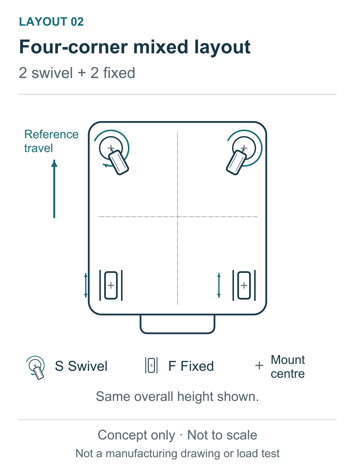
Place the fixed pair across one end, with their rolling direction aligned to longitudinal travel, and the swivel pair across the other. Use matching installation total heights for this arrangement. The fixed pair provides directional constraint, but the trolley needs room to turn; it cannot simply slide sideways on a sound floor without wheel slip. Test the intended handle end and pushing method rather than assigning a universal front or rear.
Layout 03: four swivel castors
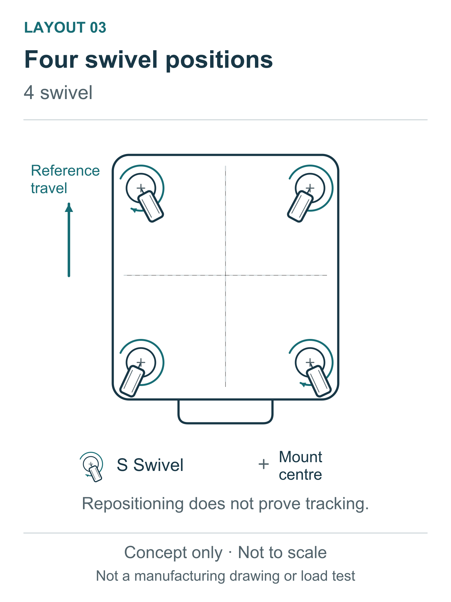
Four swivel castors let the trolley change travel direction without retaining a fixed-wheel axis. This can help with lateral docking, but the operator may need to correct its direction on a longer run. Reversing also requires the wheels to reorient. Where a directional lock is proposed, specify its alignment and engaged positions, then trial both locked and released operation. Free-swivelling behaviour alone does not prove low starting effort.
Other layouts need a specific engineering reason
The following arrangements are different geometries, rather than automatic upgrades. Read each diagram as a concept: mounting centres are not verified ground-contact points, and a swivelling wheel changes its contact position. None of these drawings establishes a support polygon, permissible centre of gravity or load rating.
Layout 01: one swivel and two fixed castors
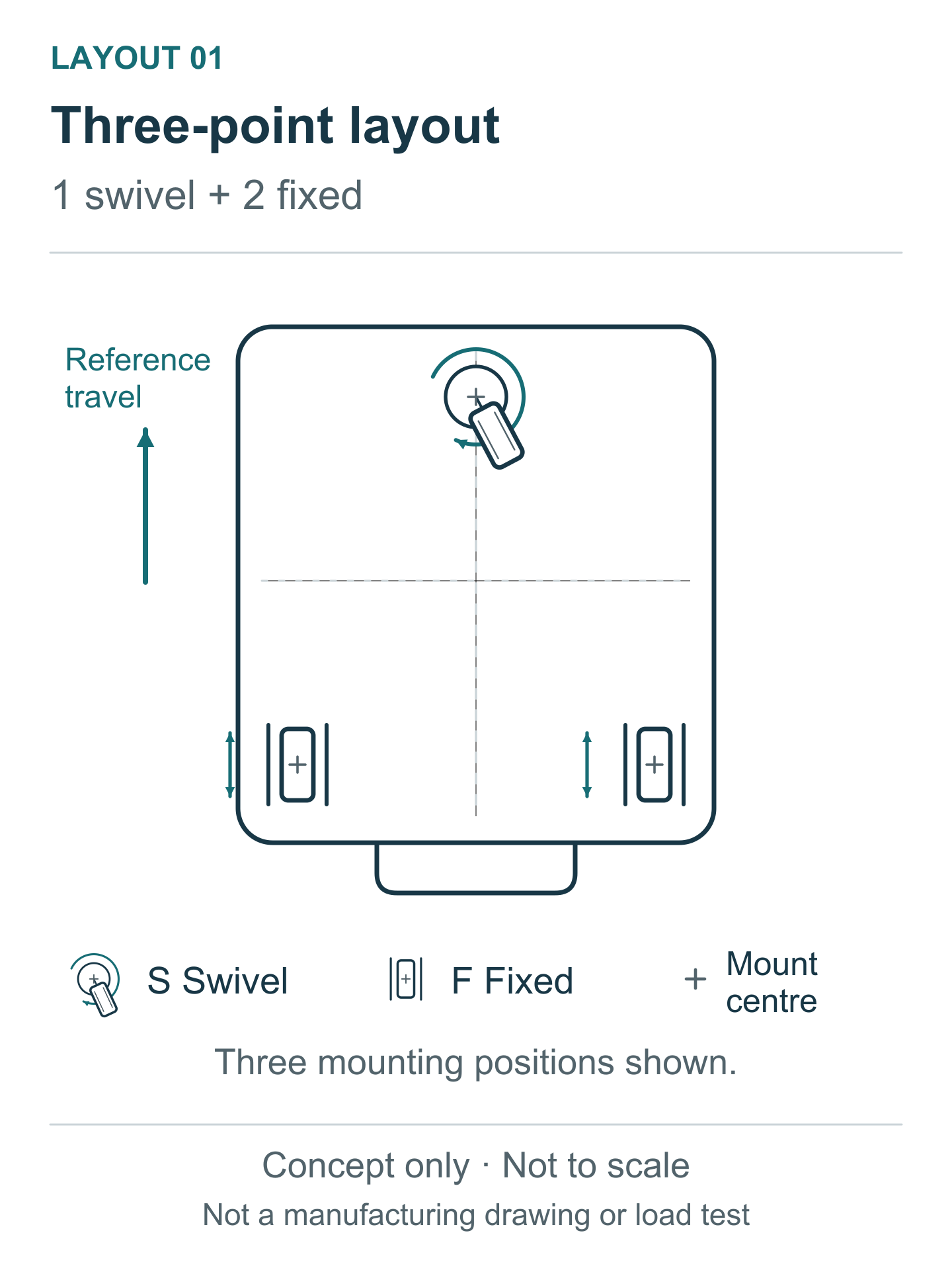
This three-point layout has one central swivel castor at one end and a transverse fixed pair at the other. It is not a three-swivel layout: the fixed pair still constrains sideways motion. Consider it only where the frame geometry and load position justify three supports. Check loading and unloading near the single-castor end, along with cornering and thresholds. Do not transfer a four-castor load assumption to this trolley.
Layout 04: two end swivels and a central fixed pair
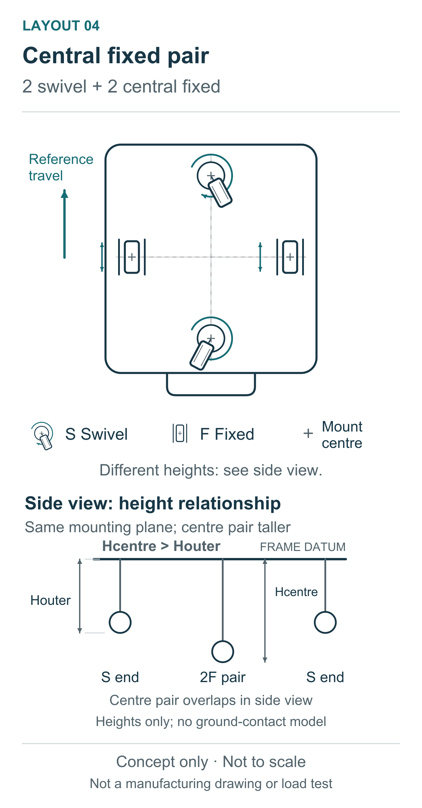
Here the two swivel castors sit at the end centres; the fixed pair sits across the middle. Measured from a common mounting plane, the central fixed pair has greater installation total height than the end swivels. It therefore projects farther below that plane. This deliberate relationship can let the frame rock between end supports, changing wheel contact as it pitches. Assess rocking, tipping risk, end loading and transitions on the actual frame and floor. A top view cannot specify the relationship. No universal height difference or towing approval follows from this concept.
Layout 05: four fixed castors with different central height
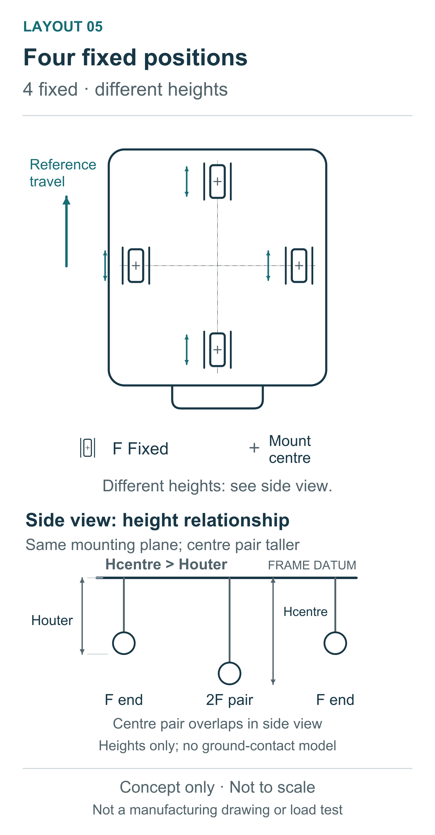
All four castors are fixed, with two at the end centres and two across the middle. All roll longitudinally. From the same mounting plane, the central pair has greater installation total height than the end pair; this is not four equal-height corner castors. If the assembly can be balanced on the central pair, opposite rolling of those wheels can permit a pivot; remaining end-wheel contact may cause scrubbing. Actual contact, steering effort, floor damage and tipping risk require assessment. Do not create the arrangement by mixing arbitrary heights. The Blickle manoeuvrability guide discusses central-height arrangements, but its configurations do not certify this trolley.
Layout 06: four swivel and two central fixed castors
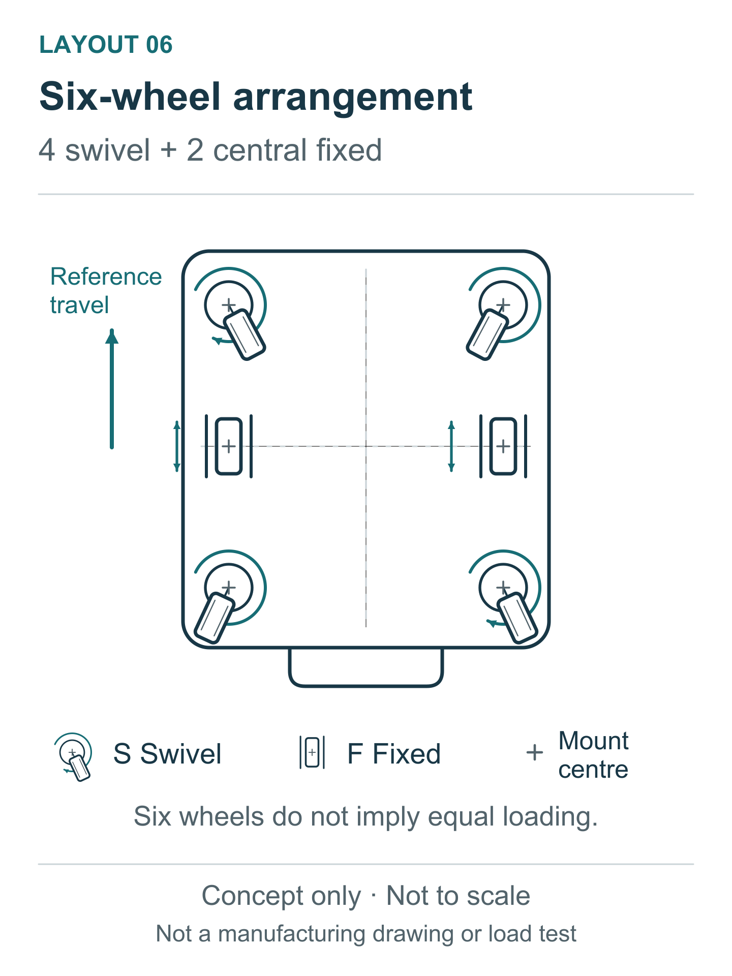
This six-wheel, equal-height concept adds a transverse fixed pair to four corner swivel castors. Establish whether the central pair maintains the intended contact on the actual floor. Frame deflection, mounting tolerances, wheel compliance and uneven surfaces affect load sharing. Six installed wheels do not mean six equal reactions. Keep the load assessment separate from layout selection; use the industrial castor load calculation guide to prepare that discussion.
Specify the movement each brake or lock controls
Swivel and fixed describe steering construction. Brakes and locks add functions; a fixed castor can also have a braking version. Avoid specifying only a braked castor without stating what must stop moving. The five states below are functional examples, rather than a claim about every Taishan model.
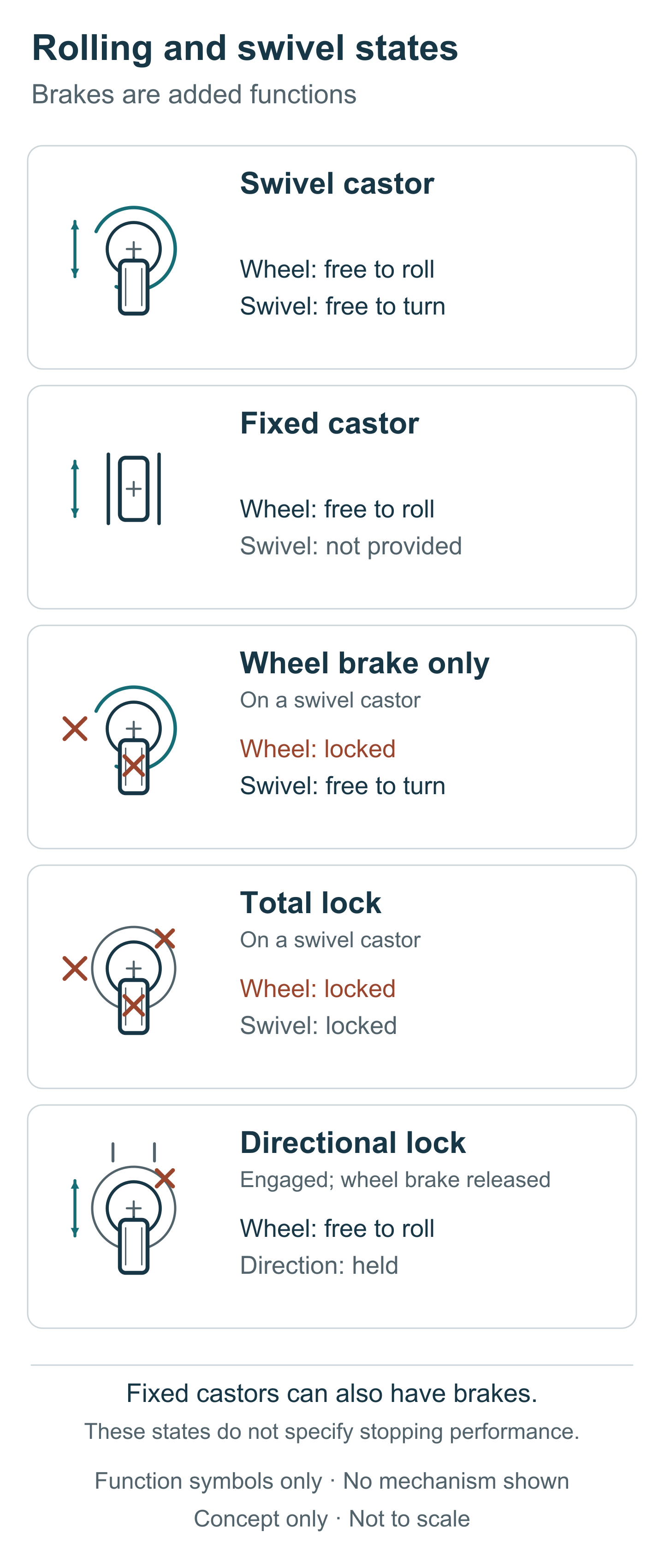
A free swivel castor rolls and swivels; a fixed castor rolls without a swivelling bracket. In the illustrated wheel-brake-only state, wheel rotation stops but swivelling remains free. A total lock stops both movements. A directional lock holds an allowed steering direction while the wheel continues rolling when its wheel brake is released. Blickle's options guide confirms the distinction between directional locking and combined wheel-and-swivel locking; actual mechanisms and available positions remain configuration-specific.
Specify parking separately from slowing a moving trolley. A parking lock is not automatically a service brake for a ramp or towing operation. Agree brake locations and quantities from pedal access, operating sequence, load condition and verified holding performance. Test access with the wheels at different orientations and the trolley docked. For interface terminology, consult the mounting, brake and directional lock guide.
Validate the complete trolley on its route
Compare candidates with the same frame, load placement, floor and operating method. Define acceptance criteria before testing. Record starting and sustained push force in N at the agreed handle position, plus the space required to turn and dock in mm. Include a start with swivel wheels facing across the intended travel direction. A steady straight run alone misses the effort needed to reorient them.
Include the worst permitted load positions, partial unloading, route joints and specified parking conditions. Inspect wheel contact and clearances, including tread-to-frame and pedal sweep. Record wheel diameter, installation total height, mounting coordinates, load position and ground clearance in mm, with the tested configuration revision. These are proposed measurement inputs, not results from the diagrams or universal pass limits. Retest a changed height, wheel construction or control arrangement before treating it as equivalent.
How to Source Reliable Castors Direct from Manufacturer
For an OEM castor specification discussion, send Taishan Castors the frame drawing, preferred layout, mounting coordinates, height envelope, load positions, route conditions and required lock states. Identify which dimensions are fixed and which can change. This lets the enquiry address the complete arrangement rather than wheel count alone.
Ask which bracket manufacturing process and dimensional checks apply to the proposed configuration, what documented test method supports its stated duty, and how an OEM/ODM change would be controlled. Agree the drawing revision, sample configuration and evaluation criteria before an order. Discuss your trolley layout requirements and request sample availability for that agreed configuration; supply terms and test evidence require confirmation.